


a) General Information:
Hydrostatic testing is the most commonly used procedure for checking the performance of pressure parts eg. vessels, cylinders, boilers, tubes etc. Hydrostatic testing is mandatory for safety of all pressure parts as it assures its strength and stability when operated under desired pressure.The following are the benefits of hydrostatic testing:
- Leak detection and its exact location. (Non-Destructive Method)
- Verification of pressure vessel design, eg. Proof & Burst pressure (Destructive Method)
The testing procedure is simple and easy. Incompressible fluids like oil and water are used for this test. The vessel which is to be examined is filled with anyone of these fluids. Very commonly water is used as a medium being most inexpensive and almost incompressible.This test will confirm leakages if any along with manufacturing defects and / or enduring change in shape of the vessel. To make leak detection easier, red or fluorescent dye is sometimes added. Safety standards normally recommend pressure testing at 150% of operating pressure and depends on regulations applied. This test is conducted for a set time period depending upon the standards.
b) Optimization of Resources:
In view of the initial capital cost, running cost and maintenance cost, it absolutely essential to optimize the specification of all the important resources.
1. Pressure :-
High pressure pump should be selected with design pressure of at least 15-20% above the max. Test pressure. A centrifugal pump when used for initial fill up should have a pressure developing capability of at least 2 bars. This will help in conducting a low pressure test which will ensure the basics of the high pressure test.
2. Capacity / Flow:-
It is absolutely important to determine the “Holding Volume” of the object to be hydro tested. The holding volume can directly lead to the optimum selection of pump flow and hence the pump model. High pressure pumps become geometrically expensive as the flow increases. Pumps with smaller flows can substantially increase the test durations especially for bigger objects. Hence, it is advisable to initially fill the object either by gravity (from the overhead tank) or by using a centrifugal pump. This is especially important when the holding volumes of the objects are larger. The normal practice is to use a high pressure pump for flows between 50 ltr/hr to 600 ltr/hr. This makes the pump smaller by size as well as by capital cost.
3. System Design :-
a) Manual :-
Manually operated option can be considered only for objects with smaller sizes and batch quantities. In this mode, the pump needs to be manually switched off when the desired pressure is achieved.
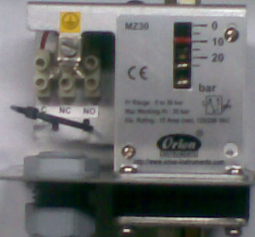
b) Automated ( Pressure Switch):-
Pressure switch helps in automatically stopping the pump as soon as the set pressure is achieved. It comes with an analog scale and calls for manual resetting which is cumbersome and time consuming. Hence, these types of systems are usually used when the test pressure is constant either permanently or at least for a substantial batch quantity.
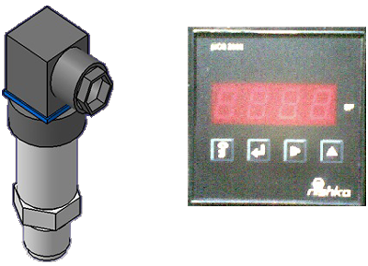
c) Automated ( Pressure Transmitter):-
PT offers a unique dual advantage of automatically stopping the pump along with easier setting of test pressure. It comes with a control unit comprising of digital pressure setting arrangement along with a digital display. Hence, these types of systems are exceptionally versatile and can be used for full operational range.
Standard Operating Procedure
Following operational sequence is highly recommended.A) Test Preparation:-
a :- Object Preparation
- The object to be hydro tested should be thoroughly cleaned from both inside and outside.
- Calibrated Pressure gauge (preferably glycerin filled) should be fitted on the object.
- Inlet and outlet should have either threaded or flanged connections.
- A non-return valve should be installed on the inlet side of the object. This will ensure retention of pressure even when either the pump is stopped or the high pressure hose is disconnected at the NRV inlet. (Testing standards call for a pressure hold-up time of minimum 15 min.)
- Water outlet should be preferably at the highest contour of the object. This will ensure forced escape of all the entrapped air inside the object. Air bubbles if left out inside may prolong the testing duration substantially.
- A Ball valve should be fitted on the water outlet side of the object.
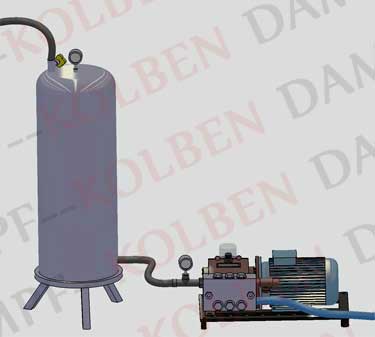
b :- Pump Preparation
- A high pressure hose of adequate operating pressure should be fitted on the pump discharge side, the other end of which is connected to the inlet side of the NRV fitted on the object under testing.
- A low pressure hose can be used on the suction side of the pressure pump.
- Proper filtration of inlet water should be ensured. An inline filter can be fitted at any convenient point between the pump suction and the water tank.
- Positive suction to the pump is highly recommended .This means that the water level in the suction tank should be above the pump level. Due to this, leakages, if any, can be easily observed as water drips out from the faulty joints.
- A Pressure gauge (preferably glycerin filled) should be fitted on the pump discharge side.
- Proper electrical connections should be ensured for the pump prime mover (Motor).
- Pump and motor specifications should be verified prior to the beginning of pressure test. (Pump flow, max. pressure, motor HP/speed etc.)
- High pressure pistons/plunger pumps can developer infinite pressure. Operating pressures above the pump design pressure can instantly cause a severe damage to the pump / object under testing. Full closure of the ball valve on the water outlet side shall result in developing pressures above the required max. Pressure as well as the pump design pressure. To avoid this, these pumps are automated using a pressure switch or a pressure transmitter which automatically stops the pump as soon as the desired test pressure is achieved. A bypass with a needle valve should be provided on the pump. This needle valve in the bypass line should be used as a throttling valve to achieve the desired pressure. This bypass system avoids the sudden rise in the pressure caused due to the surge in the discharge line.
B) Testing Procedure:-
- Bigger objects should be initially filled with water either by gravity or with the help of a centrifugal pump. (Centrifugal pumps normally deliver high flows but can develop comparatively low pressures).
- During this fill-up, the ball valve on the water outlet side should be kept open till the time all the entrapped air inside the object is pushed out.
- When a clear stream of water (w/o entrapped air) is observed coming out of the water outlet, the ball valve should be slowly closed.
- It is a MUST that the throttling valve (needle valve) in the bypass line is fully opened before the pump is started.
- The piston/plunger pump, now, can be started.
- To begin with, all the pump discharge shall take the bypass route. The throttling needle valve being fully open shall not develop any pressure in the line (the pressure gauge may not show any significant reading). This valve, now, should be throttle slowly and carefully to built up pressure in the pump discharge line and hence within the object. This pressure built up can be seen on both the pressure gauges (on the pump as well as on the object). Alternately, a throttling valve can be installed instead of the ball valve on the water outlet side and can be operated slowly and carefully till the time desired test pressure is achieved. The flip side of this option is that the pump has to be in running condition for the entire test duration.